Robotic Arm with Machine Vision

I designed and built a 5.5 degree of freedom robotic arm capable of recognizing, picking, and colored cubes. The arm is was built for just under 50$ illustrating how accessible robotics has become in modern times
Project Goals & Background
While taking an Intro to Robotics course, I was given the option to pursue an independent project for extra credit. Drawing on my experience as a Teaching Assistant working with robotic arms, I chose to design and build my own from scratch to deepen my understanding of how they function and what goes into constructing them. I set the following goals for the project.
-
Design, Manufacture, Assemble, and Program a working Robotic arm with end effector
designed to pick up a specifically sized cube -
Design software to recognize two colored cube and determine their poses within a known coordinate system.
-
Design program and controls system to guide arm’s movement to pick up and move cube to specified location based color

Initial Sketch of Setup and End Effector
Physical Construction & CAD Design
Degrees of freedom (DoF) refer to the number of independent movements a robotic arm can perform. More degrees of freedom allow for greater dexterity, enabling the arm to reach and manipulate objects in more complex ways. However, this comes at the cost of increased control complexity, both in terms of hardware and software. Fewer degrees of freedom simplify control and design but limit the range of achievable movements.
For this project, I chose to make a 5-DoF robotic arm—waist, shoulder, elbow, wrist, and gripper rotation—which I determined to be the minimum necessary to complete the task effectively. This configuration is ideal for picking up cubes, as it allows the arm to position itself directly above a cube and rotate the gripper to align with the cube’s orientation. (Try to imagine this with your arm!)

I designed the above model in SOLIDWORKS, drawing inspiration from a wide range of existing arm designs.
The end effector is based on a widely adopted two-finger configuration that uses a parallel linkage mechanism to convert motor rotation into linear finger motion. I designed and simulated the mechanism using GearMates constraints in SOLIDWORKS to model the motion and validate the sizing of each component.

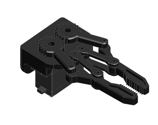
End Effector Design (Open Left, Closed Right)
Actuator and Motor Selection
To control each of the robotic joints, I considered three types of motors: Servos, Stepper Motors, and Brushless DC Motors (BLDCs).
-
Servo Motors offer built-in closed-loop control, which makes them easy to use and accurate. However, they are typically limited to a rotation range of less than 270 degrees, which restricts their flexibility.
-
Stepper Motors are highly precise due to their ability to move in fixed increments (steps) controlled by pulse signals. They also provide strong torque, but require careful control to achieve the desired position, especially over longer rotations.
-
Brushless DC Motors (BLDCs) can achieve higher rotational speeds (RPM) and are well-suited for fast-moving applications. Like steppers, they lack inherent position control and require additional sensors or feedback systems for precise angle control.


Motor Selection (NEMA17 Stepper Left, MG996R Servo Right)
I chose a stepper motor to rotate the base because it needs to rotate more than 180 degrees—something most servo motors can't handle. Additionally, the stepper provides sufficient torque to handle the large forces generated when the robotic arm extends outward and cantilevers its weight. For all other joints, including the gripper, I selected servo motors. Servos were chosen for their built-in closed-loop control, which allows them to accurately reach and maintain specific angles in response to PWM signals.
Why not use steppers for the whole thing?
-
Steppers with encoders are extremely expensive (costing around 50$ per unit) and the extra torque they could provide isn't necessary since this arm only has to pick up small plastic cubes.
Why not use servos for the whole thing?
-
Standard servos like the MG996R are limited to a range of about ±90°, which becomes a constraint for the base rotation.
-
To increase torque, I also implemented a gear reduction (1:4) on the base, this would have prevented a servo from even achieving a full 45° sweep.
Why not use BLDCs at all?
-
I already had the other motors on hand. Within a limited 8-week project timeline, it simply made more sense to go with what I had and was familiar with already. In a real world project, I would have put more consideration into using BLDCs.

Base of Robot Crossection. Gearbox with Stepper Gear (Red) and Base Gear (Blue) highlighted. Gear ratio is 27:108 = 1:4
The ultimate goal of this project is to detect colored cubes and sort them based on color using the arm. To achieve this, the system must not only recognize different objects, but also determine each object’s pose (its position and orientation) relative to the robotic base. I accompolished this by creating a vision pipeline, a kinematic solver, and a motion planning system
-
Vision Pipeline: Software and Hardware solution to "see" the colored cubes and determine their location and orientation relative to the Robot Base
-
Kinematic Solver: Software that calculates the joint angles needed for the arm to reach a specific position. Given the pose of the cube, it determines how the robotic joints must move to align the gripper for pickup.
-
Motion Planning: Software to coordinate the robot's actions. It uses input from the vision system and the kinematic solver to generate smooth, efficient movements that execute the full pick-and-place routine.
The figure below shows how I structured the software and hardware to achieve this:
System Software Overview
(1) The object is placed on a calibration checkerboard to establish its position relative to the scene. (2) An iPhone captures live video, which is sent to MATLAB. (3) MATLAB performs distortion correction, object detection, and pose estimation, then calculates the required joint angles. (4) These angles are transmitted via serial to an ESP32, which commands the servo controller to move the robotic arm.

System Software Detailed
For interested engineers, read on; otherwise, you can skip to the Results section. This section provides a more detailed look at the inner workings of the system—from the math behind camera calibration to the logic driving the robot’s movement.
The process can ultimately be broken down into 3 main steps as previously explained:

Inner workings of the Robotic Arm Code consisting of three main parts: Image Processing, Kinematics, and Interpolation.
1. Image Processing
Image processing transforms raw camera input into actionable data. The goal is to find the position and orientation (also known as the pose) of colored object. I achieve this by using an iPhone camera connected directly to MATLAB.
Camera Calibration - Intrinsic and Extrinsic Parameters
Before any object can be located accurately, the camera itself needs to be understood. The program first runs calibration by capturing an image of a standard calibration plate (a plate with intersective white and black tiles) in which every tile shares the same height and width.
Knowing the board must be flat, the program can account for lens distortion. Additionally since the size of each square is known, the camera can determine the camera's intrinsic parameters (focal length, image center, resolution) and extrinsic parameters (its position and orientation relative to the scene). Which are necessary to extract the positional data from the image.
Object Detection - Edge Detection
With calibration in place, the system moves on to detecting objects based on color. It uses RGB thresholding to identify regions of red and green, creating binary masks that isolate each color. These masks are processed using built-in MATLAB component analysis (bwlabel and regionprops) to identify the main object in each color — extracting its centroid, bounding box, and orientation angle.
Mapping to Real World Coordinates
Once the object is detected, its centroid is mapped from image space into world coordinates using the camera calibration data. These coordinates are then adjusted to align with the robotic arm’s coordinate system.
Calibration Image

Binary Mask Program to detect Green and Blue Objects


Pixel coordinates, which lie on a 2D image plane, are mapped to 3D world coordinates using the projection formula shown. Once the camera’s intrinsic matrix is known (obtained during calibration) the 3D position of the object can be solved using LU decomposition.
2. Kinematics
To successfully pick up colored cubes, the robotic arm must precisely calculate how each joint should move so that the gripper reaches the cube’s location and aligns with its orientation. In Robotics this process is called inverse kinematics. Recall that the Arm consists of 5 degrees of freedom (DOF):
-
θ₁ - base rotation
-
θ₂ - shoulder
-
θ₃ - elbow
-
θ₄ - wrist pitch
-
θ₅ - wrist rotation
These angles are computed using a blend of geometric and trigonometric methods, beginning with the calculation of the horizontal distance from the base of the arm to the target position. The base rotation angle, θ₁, is determined using the arctangent of the target’s x and y coordinates, allowing the arm to face the object. The elbow angle, θ₃, is then calculated using the law of cosines, based on the triangle formed by the arm’s upper and lower links and the straight-line distance to the target.
Next, the shoulder angle, θ₂, is found by first computing the total angle from the base to the target, then subtracting the elbow’s contribution, ensuring the arm bends naturally toward the object. To keep the gripper vertically aligned, θ₄ is used to offset the combined angles of the shoulder and elbow. Finally, θ₅ adjusts the wrist’s rotation to match the orientation of the object, allowing for a properly aligned grasp.


Geometric relationships and trigonometric formulas used to compute each of the five joint angles. Variables like the horizontal distance (R), vertical height (Z), and intermediate angles (α, β) are used to solve for shoulder and elbow positions, while base rotation and wrist alignment are derived from planar orientation.
3. Trajectory Generation & Interpolation

.png)

With the vision system, kinematics, and control in place, the robot is now capable of determining the joint angles needed to pick up an object. However, commanding the joints to move directly from one position to the next results in abrupt, unnatural motion—snapping instantly between poses.

To address this, joint motion must be interpolated—broken into a sequence of smaller steps that guide each motor smoothly between positions. Among several trajectory planning methods, I chose to use quintic polynomial interpolation, which is a fifth-degree function defined by six constraints: initial and final position, velocity, and acceleration. These values allow one to determine the polynomial’s coefficients (a₀ through a₅), which describe the shape of the motion curve. Once calculated, these polynomials can be evaluated at any time point to retrieve the corresponding joint angle, creating fluid transitions between poses.
Base quintic polynomial and initial values. Velocity and Acceleration at Start and End points is set to zero.
Image Gallery and Results


The First Video illustrates movement and movement interpolation. The reason for all of the different colors is because I had to reprint components many times! The arm ended up being too heavy for the servos to move, so I had to lower the infill and also add pockets to reduce weight.
The Second Video shows the complete pick-up and drop-off routine, using two different colored erasers to represent cubes. The arm moves above an eraser, picks it up, and then drops it off the edge of the table.
Random photos of the Robot Being Built


Theres so much more I could talk about, but it would be too much to write and much easier to talk about in person! If your interested please reach out