The Cardboard Companion
Ever receive a package from Amazon with a hilariously oversized box? You're not the only one...every year millions of tons of cardboard are wasted due to excessive packaging. My senior design team tackled this problem by making a custom-sized cardboard box cutter.
The system produces precisely fit cardboard boxes accurate to approximately ±1cm.
Project Goals & Background
During my final year of college, I joined a Senior Design team tasked with developing a custom cardboard-cutting machine for a hypothetical small business owner in the shipping and packaging industry. This business handles everything from fragile items to heavy-duty products and aims to modernize its process by integrating an automated system that folds and recycles cardboard into custom-fit boxes.
Key project goals included:
-
Accurately scanning objects
-
Determining optimal box dimensions
-
Scoring and cutting raw cardboard
-
Folding it into a finished box
Benchmarking and Pugh Matrices
With clearly defined project goals, our next step was selecting the best approach for each task and implementing it. Since cardboard packaging is a well-established industry, there are numerous existing methods for object measurement and box cutting. Our challenge was to choose the most effective solutions that fit within our $500 budget and allowed for system adaptability.
To do this, we used Pugh matrices—a decision-making tool that compares different options against a set of weighted criteria. We applied this method to each subsystem, including object scanning, box sizing algorithm, cutting, and folding.


Pugh Matrices for the 4 main subsystems of the Cardboard Companion


Objects are scanned by an ultrasonic sensor to determine their exact length, width, and height (bounding box). These will be passed to the next stage to generate a precisely fit cardboard box.
The dimensions of the flattened box are calculated to minimize cardboard usage. Different combinations of depth, width, and length are tested to find the box configuration that uses the least material. Once the optimal layout is selected, a geometric pattern is generated. This layout is then converted into G-code, which controls the machine's toolheads—moving, rotating, raising, and lowering them as needed
The G-code instructions are executed by a CNC-style mechanism, where the cutting blade and scoring wheel, which move in coordination to cut and crease the cardboard, resulting in a precisely manufactured custom-fit box.
Finally, the object(s) are placed into the custom-cut box, which is then manually folded along the scored lines and sealed with tape, completing the packaging cycle.
The Solution
Full System Demo


My Role: End Effector
I had to design and refine most of the mechanical components related to Cutting and Scoring. One of the most challenging was the end effector, which required multiple degrees of freedom (such as rotation and vertical tool movement) while remaining rigid enough to avoid deflection during use and maintaining a balanced CG.
The end effector utilizes linear actuators each attached to a servo motors to raise, lower, and rotate the tool heads in the correct orientation. I ended up going through three main revisions. Major changes in Revision B included repositioning the blade and scoring wheel to opposite ends of the bar, rather than having them on the same side. This adjustment was made to improve the system’s balance, which previously suffered from wobbling

Two major revisions for the Sliding Mechanism
Another challenge was working within a limited budget of $500, which prevented us from purchasing OTS linear rails. As a result, we had to design our own. The Final Revision of the end effector was modified to a V-wheel cart system, which significantly improved stability and reduced friction compared to the initial rail design.

Three major revisions for the end effector
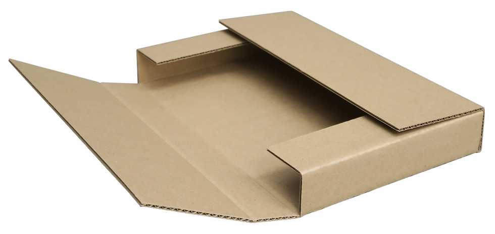
Given the constraints of our budget and system complexity, we ultimately chose the One Piece Folder (OPF) box style. The OPF design is significantly simpler to cut and fold, making it more practical for our limited prototyping resources. While it is less efficient in terms of material usage, the simplicity of the folding mechanism made it the best fit for our proof-of-concept system.
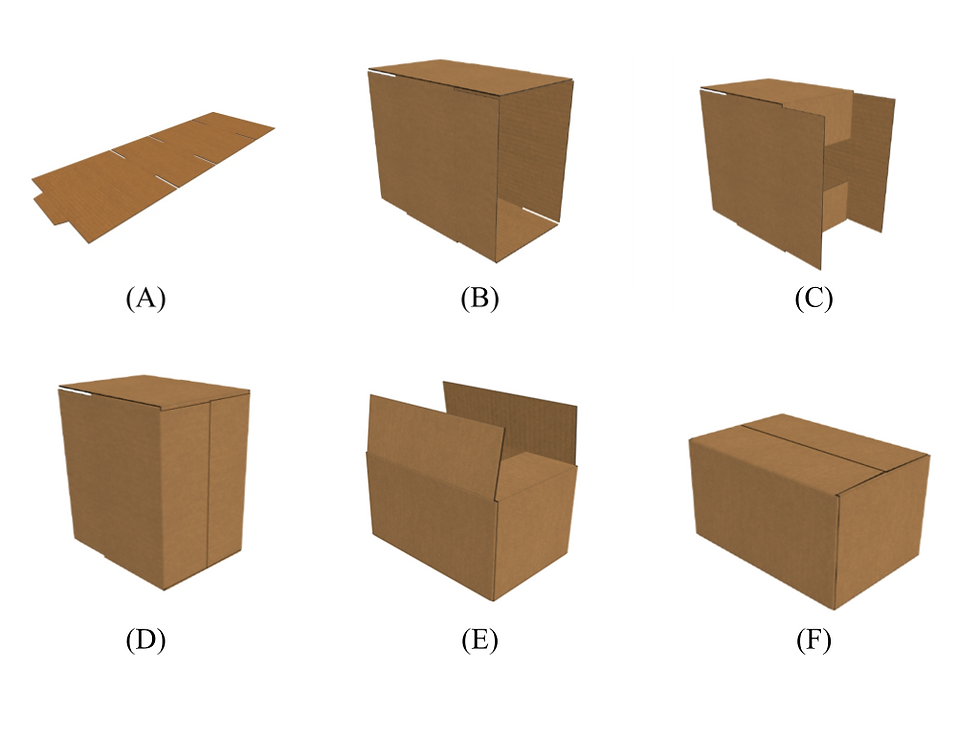
Among the designs tested, the Regular Slotted Container (RSC) was the most efficient in terms of both metrics. It uses most of the available cardboard area and provides a high box volume relative to its cutout size, which explains why they are so common. However, its assembly process is relatively complex: the box must first be folded into a tube shape and then sealed along an edge with staples or adhesive. This introduces added mechanical complexity and makes it harder to automate on a budget.
As part of the design process, I was responsible for selecting the type of cardboard box our system would cut and fold. Packaging comes in a variety of box styles, each with its own trade-offs. To determine the most suitable option, I considered two main factors: material efficiency (measured as cardboard area per unit of enclosed volume) and ease of folding for automated manufacturing.
To aid in this decision, I created a spreadsheet that analyzed the material efficiency of several common box designs. The two main metrics I considered were:
-
Material Usage: How much of the cardboard sheet is actually used in the final cutout, compared to the total area. A more efficient design minimizes leftover scrap.
-
Volume Efficiency: The ratio of the box’s internal volume to the area of the uncut, unfolded sheet. This shows how effectively the cardboard is converted into usable volume.
My Role: Cardboard Box Selection
Selections from Spreadsheet. Most important metrics are rightmost columns "Material Used" and "Efficiency"

Regular Slotted Container (RSC) Assembly Steps
One Piece Folder Box
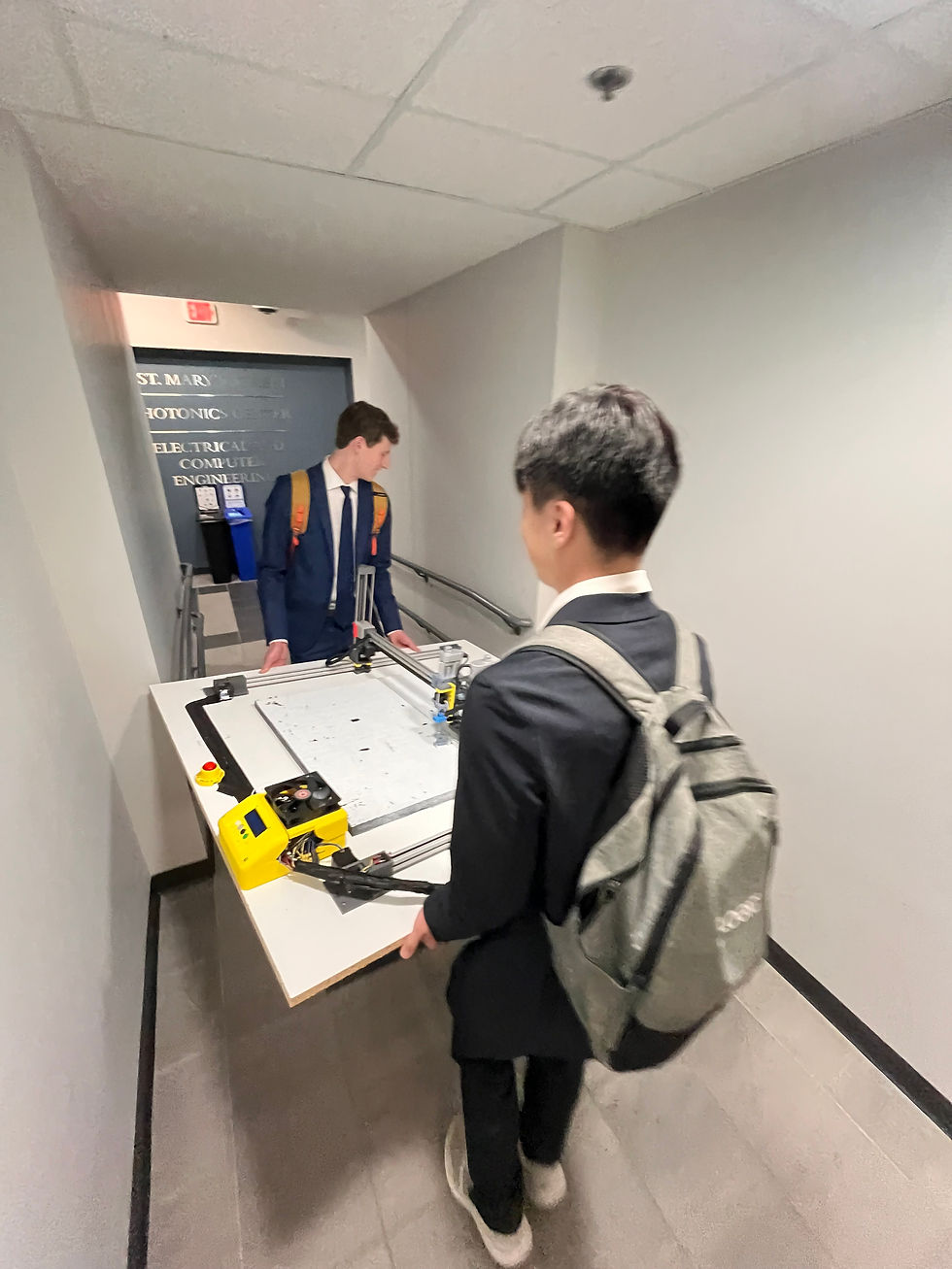
Transporting the Cardboard Companion to our Senior Design Presentation (Human For Scale)